MPGuino
Arduino Communications Page
Any questions or comments, send them to - combustor@combustory.com
Contents |
Summary
This is an impressive use of the Arduino platform. One that will actually pay for itself too. A small group of folks banded together and created an open platform called http://www.openguage.com where you will not really find much information concerning this device, but there is lots of information in a forum at http://www.ecomodder.com, where you will find tons of useful and fun ways on improving gas mileage for any car. To explain what these folks did for the average working Joe, who can't quite afford a car newer than 1995, is just amazing.
They came up with a way to build a reasonably low-cost device that will gauge your MPG, even for cars that do not have an OBD-II interface in there car. At the moment it is restricted to use in cars with fuel injection, but given enough time they may even find a way to gauge cars with carburetors. To cut to the chase, this device uses inputs from the Vehicle Speed Sensor(VSS) and one fuel injector control wire, both of which are easily found in just about all fuel injected cars, minus mechanical fuel injection, which only Mercedes seemed to make reliably albeit expensively. So, sorry all those 300E owners, you can't play with this toy right now.
The device sports an LCD screen with several features. (Note: Describe features here)
Functional Description of the Solution
To further detail the solution, the VSS provides a pulse input related to the speed and distance traveled, meaning from this sensor you know how fast the car is going from the pulse frequency and how far the car has traveled by counting the actual number of pulses. Pulses per mile vary from car to car and based on the forum I saw a range in the 4,000 - 10,000 pulses per mile. The injector control wire provides the fuel flow mass. By making the relation of the known flow rate of an injector and the amount of time that the injector is turned on, you can calculate the the actual fuel mass flow rate your car is using.
On the electronics side they used the Arduino platform as the microprocessor and threw in some supporting components to prevent small fires that create anger and horrible smells. I hate the smell of fried electronics, unfortunately I know it too well. The microprocessor polls the sensors in the micro-second realm, and writes the results to the LCD in the 1/2-1 sec. realm. This gives the user a near real time view of the actual data.
There really is not much at the high level design function, but as they say, "The Devil is in the Details".
Requirements and Knowledge
- Basic soldering and electronic building skill
- The following parts list for the Arduino assembly
- 2 5.1v zener diodes
- 1 2n3906 PNP Transistor
- 1 220 ohm resistor
- 2 100k resistors
- 3 tactile switches
- 1 freeduino arduino clone (any arduino can probably be made to work) i.e. an iduino: http://spiffie.org/kits/iduino/ or a Freeduino
- 1 LCD (others might work as well, check pinout and chipset, etc). 16x2 LCD Module While Characters Blue Backlight Or a green one from sparkfun or mouser (a number of folks like the green ones better)
- Sufficient Perfboard
- A case to hold it all together
- Additional parts for the iDuino assembly
- 1 7805 Voltage Regulator
- 1 1n4004 diode
- 330 uf cap
- 1 .1uf cap.
- You will need to find the wires for the VSS on the vehicle computer or control unit.
- If you're lucky you won't need much troubleshooting skills
Assemble the Electronics
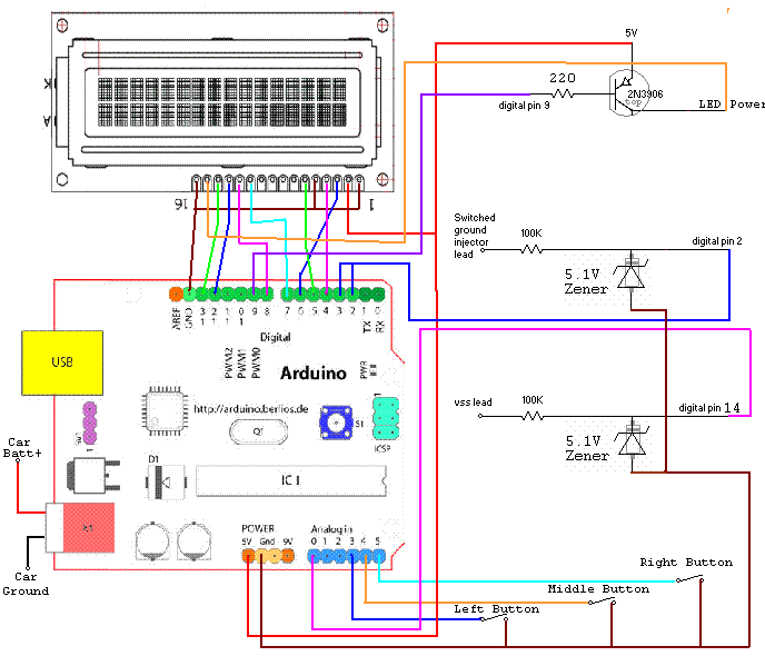
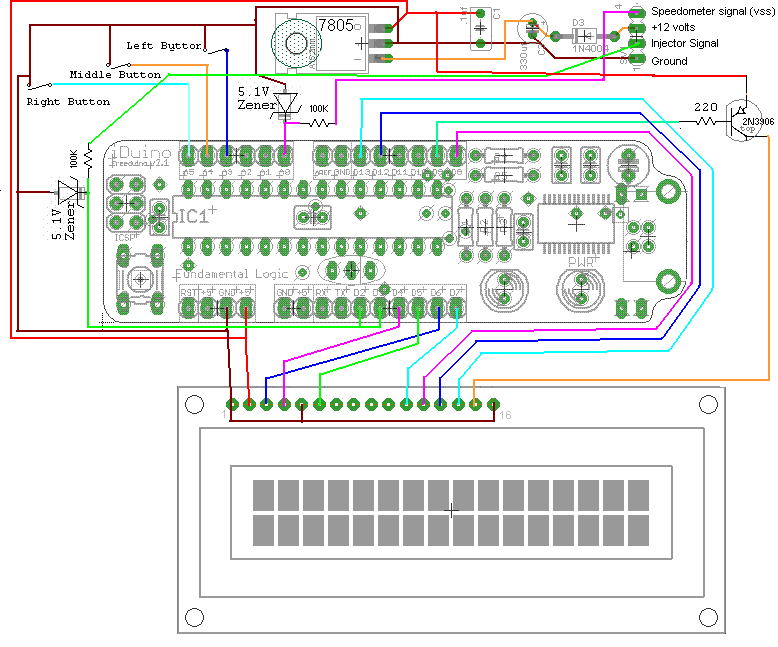
Here are the schematics. This should be enough for most of you. There are two assemblies that are possible to build. The Arduino or the iDuino. The LCD screen is at the top of the schematic and note the only two output leads for the VSS and the injector.
Arduino Assembly Schematic
Arduino Assembly Schematic

